
Why Sight Flow Indicators Are Critical For High- Pressure Industrial Systems

In highly automated process plants across European countries like Germany, France, and the Netherlands, control rooms rely heavily on digital sensors, flow transmitters, and complex PLC systems. Yet, even the most advanced digital network has a single point of failure: it only tells you what the instrument thinks is happening inside the pipe. When a sensor drifts, fouls, or loses power, field operators need a definitive, unarguable way to verify process conditions safely.
This is where Sight Flow Indicators become irreplaceable safety and operational assets. By providing a direct, physical window into the process line, these robust mechanical devices allow operators to visually confirm fluid movement, direction, color, and clarity.
In high-pressure applications, however, a sight indicator is much more than a simple piece of glass bolted to a pipe it is a pressure-containing vessel that must withstand extreme thermal and mechanical stresses. Choosing the wrong design or material can lead to catastrophic line breaks, making a deep understanding of indicator engineering vital for plant safety and efficiency.
The Hidden Risks of High-Pressure Flow Monitoring
High-pressure industrial systems leave zero margin for error. In industries such as chemical processing, oil and gas, and power generation, fluids are frequently transported at elevated temperatures and pressures exceeding 100 bar.
Avoiding Catastrophic Instrument Failure
The primary engineering challenge in these systems is maintaining structural integrity while offering a clear view. Standard industrial glass can quickly cloud, erode, or fracture if exposed to rapid pressure spikes, thermal shock, or corrosive media like caustic soda and acids.
A failure in a high-pressure line doesn't just mean a small leak; it can result in a high- velocity jet of hazardous fluid or explosive decompression. Field operators rely on these indicators during critical phases such as pump startup, pipeline purging, and batch mixing to ensure that valves are correctly aligned and that fluids are moving as intended. Without physical verification, a blocked line or a cavitation issue can destroy downstream pumps and compressors before the control room even flags an anomaly.
Selecting the Right Indicator Style for the Job
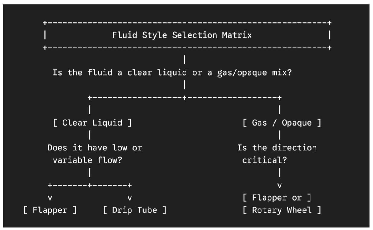
Not all fluids behave the same way inside a pipeline. A clear liquid requires a different visual aid than a dark hydrocarbon or a high-velocity gas. When sourcing equipment from a reliable Sight Flow Indicators manufacturer, you must match the internal indicator mechanism to the specific fluid dynamics of your process.
1. Flapper Indicators
Flapper styles feature a hinged metal indicator inside the stream that lifts in response to fluid flow. These are ideal for both horizontal and vertical lines carrying clear or semi-opaque liquids. The angle of the flapper gives operators a rough estimate of flow velocity, making it easier to spot line restrictions or pump performance drops.
2. Rotary Wheel (Propeller) Indicators
Rotary indicators use a small impellor or propeller that spins as fluid passes through. These are particularly effective for clear liquids and gases moving at low to moderate velocities. Because the spinning motion is easily visible from a distance, they are highly favored in busy process bays where operators cannot always stand right next to the line.
3. Drip Tube Indicators
For gravity-fed lines, distillation processes, or low-flow applications where liquid trickles through the pipe, a drip tube style is essential. It forces the liquid to drop vertically past the glass windows, preventing the fluid from simply running along the bottom of the pipe unobserved.
4. Plain (Ball / Visual) Indicators
When the fluid color, turbulence, or presence of bubbles is enough to confirm flow, a plain indicator without internal moving parts is preferred. This style minimizes pressure drop across the device and eliminates internal components that could clog when handling fluids with suspended solids or high viscosity.
Sizing and Engineering Considerations for High-Pressure Applications
Designing a high-pressure sight flow indicator requires careful consideration of metallurgy, glass composition, and sealing technology. As an established Sight Flow Indicators supplier in Europe, Bliss Europe engineers these devices to meet strict operating limits.
Glass Metallurgy: Borosilicate vs. Quartz
Standard soda-lime glass is entirely unsuitable for industrial process lines. High- pressure indicators rely on toughened borosilicate glass, which offers exceptional resistance to thermal shock and chemical attack. For extreme temperature applications (exceeding 300°C), quartz or sapphire glass may be specified to prevent thermal cracking.
Additionally, when dealing with steam or highly alkaline fluids that can etch glass over time, engineers should install protective mica shields between the process fluid and the glass window.
Gasket Integrity and Bolting Torque
A sight flow indicator is only as secure as its sealing arrangement. High-pressure designs utilize independent, recessed gasket pockets that prevent gasket blowout under pressure spikes. The bolting configuration must distribute loading forces evenly across the glass perimeter to avoid creating localized stress points that could cause premature glass failure.
The European Context: Compliance, PED, and Safety Standards
Executing industrial projects in countries like Belgium, Spain, Germany, or Norway requires total alignment with European Union directives.
PED 2014/68/EU and CE Marking
Because a sight flow indicator is a pressure accessory, it falls squarely under the jurisdiction of the Pressure Equipment Directive (PED). Depending on the pipe size (DN), maximum allowable pressure (PS), and the hazardous nature of the fluid (Group 1 or Group 2 gases/liquids), these indicators must be evaluated under specific conformity modules. For high-pressure installations, this often requires Category II or III compliance, backed by third-party verification from a Notified Body and an official CE marking.
Harmonized Design Codes
Engineers must verify that the pressure containment body is designed according to recognized codes like EN 13445 (unfired pressure vessels) or ASME Section VIII. Utilizing a supplier that offers dual-certified products ensures that your equipment passes local European site inspections while adhering to the global design practices preferred by major EPC contractors.
Industrial Use Cases
Oil & Gas / Petrochemical Systems
In offshore installations in Norway or refineries in Rotterdam, sight indicators are used on lube oil consoles for large turbines and compressors. A sudden drop in lube oil flow can cause millions of Euros in equipment damage; a rotary indicator gives field teams instant confirmation that the bearings are receiving lubrication.
Chemical Processing Plants
Chemical plants in France and Italy use these indicators on hazardous reagent lines. By observing the fluid color change through the glass, operators can verify that a chemical reaction has occurred or that a rinsing cycle has successfully cleared the piping system.
Power Generation Facilities
High-pressure boiler feedwater lines use drip tube or flapper indicators to monitor condensate return lines. Spotting a steam trap failure early via a sight indicator prevents water hammer and thermal stress in the main boiler tubes.
Frequently Asked Questions
What is the maximum pressure limit for a high-pressure sight flow indicator?
Depending on the size of the window and the body design, industrial high-pressure indicators can be engineered to handle pressures up to 150 bar (ANSI Class 600 or 900) or higher, provided they use extra-thick toughened borosilicate glass and reinforced metal retaining caps.
How do I prevent the glass from clouding in steam applications?
Steam lines tend to leach silica from borosilicate glass, causing it to become cloudy or cloudy over time. To prevent this, always specify a mica shield, which acts as a physical barrier protecting the internal surface of the glass from direct contact with high-temperature steam.
Can sight flow indicators be installed vertically?
Yes, but the choice of internal indicator matters. Flapper and rotary styles generally work well in both horizontal and vertical upward flow lines. However, drip tube indicators are strictly designed for vertical downward flow lines under gravity or low pressure.
What is the difference between a sight flow indicator and a sight glass?
While the terms are often used interchangeably, a sight glass usually refers to a window welded or bolted directly onto a process tank or vessel to check liquid level. A sight flow indicator is a dedicated inline pipe fitting designed specifically to show the movement and condition of a flowing process fluid.
Conclusion
Digital automation has transformed modern industrial manufacturing, but it cannot entirely replace human eyes on the factory floor. High-pressure Sight Flow Indicators provide the ultimate safety net for plant operators, offering unambiguous confirmation of process states when electronics fail. By selecting the correct indicator style, focusing on high-grade material traceability, and ensuring full compliance with European PED and CE regulations, you can significantly mitigate risk and keep your industrial operations running safely.